


Min.Order : 1 Pieces Quick Quotation >
Conpany Profile
Product Details
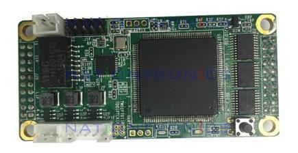
SOM205
1.Features
SOM205 is one of our truly latest promoted series products: SOM (System on Module). As to the limitation of space, protection of screens, after-sales service and price, SOM204 card provides perfect solutions. And will also provide competitive advantage for the design of differentiated products.
The module designed with SOM205 must work with TP201/TP205(Switch). The function of TP201/TP205 is to transfer the gigabit signal from sending card into 100mbps signal.
SOM205 is mainly applied to normal screen with pixel pitch smaller than 4mm.
The followings are the features:
1.Has all the functions of the 9th generation receiving card;
2.Single card supports 6 groups of RGB parallel-data signal, 16 groups of serial-data output and 4 way clock signal;
3.Supports high refresh rate and high gray scale(up to 65536 level);
4.Supports general chip, PWM chip and other common Led driver ICs;
5.Supports any type of scanning mode(within 64) and other serial decode scanning mode using 74HC595 and so on;
6.Supports brightness and color pixel-by-pixel calibration;
7.Single card supports up to 65536(256*256) pixels; the refresh rate (module with 128*128 pixels, pixel pitch smaller than 4mm, scanning mode between 32-64)can reach to 2400HZ; brightness can be adjusted manually;
8.Supports single-card color space conversion;
9.Supports configuration file read-back;
10.Requires only one twisted pair in Cat5e cable to convey signal, thus video signal and power can transfer with only one cable;
11.Requires only two differential lines; the basic frequency is only 25Mhz, and can reduce the interfere caused by the flat cable.
12. Irregular led screen configuration: position of one card can be set as needed, and image driving by one card can be rotated in four directions;
13. Supports 100Mbps signal hot-backup;
14.Circuits of LED panel and SOM card can be integrated on one section, which is easy for repairing and saving money for after-sales service;
15. Compliant with RoHS;
16.Compliant with CE-EMC: with a totally enclosed shielding case, the card can prevent electromagnetic interference, and pass EMC test easily; the small size provides a better condition for water-proof design.
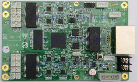
2.Application of circuit


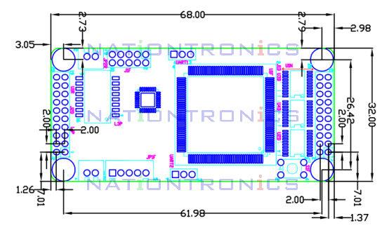
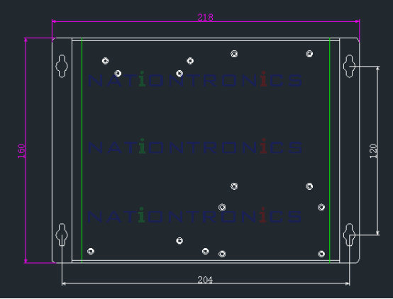
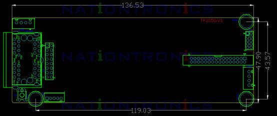
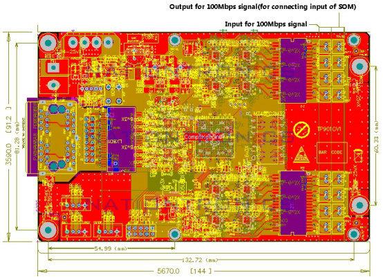
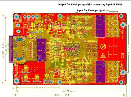
3. Dimensions
You can design your own dimensions according to the schematic diagram from Linsn, so there’s no fixed dimensions. Compared with traditional receiving card, such solution provides a more convenient and flexible way to make a led screen as any requests.

6-group RGB parallel-data as follows:
J1O | |||||
| R1 | 1 | 2 | G1 |
|
| B1 | 3 | 4 | R2 |
|
| G2 | 5 | 6 | B2 |
|
| R3 | 7 | 8 | G3 |
|
| A | 9 | 10 | B |
|
| C | 11 | 12 | D |
|
| E/G6/ | 13 | 14 | F/CLK2 /B6 |
|
| GND | 15 | 16 | LAT |
|
| CLK | 17 | 18 | SR |
|
| OE | 19 | 20 | GND |
|
J2O | |||||
| GND | 1 | 2 | OE_B/CLK4 |
|
| VCC | 3 | 4 | VCC |
|
| GND | 5 | 6 | GND |
|
100mbps differential signal+ | DB_P | 7 | 8 | DB_N | 100mbps differential signal- |
100mbps differential signal+ | DA_P | 9 | 10 | DA_N | 100mbps differential signal- |
| UART_TX | 11 | 12 | UART_RX |
|
| B3 | 13 | 14 | R4 |
|
| G4 | 15 | 16 | B4 |
|
| R5 | 17 | 18 | G5 |
|
| B5 | 19 | 20 | R6 |
|

16-group serial data mode as follows:
J1D | ||||||
| data0 | 1 | 2 | data1 |
| |
| data2 | 3 | 4 | data3 |
| |
| data4 | 5 | 6 | data5 |
| |
| data6 | 7 | 8 | data7 |
| |
| Ao | 9 | 10 | Bo |
| |
| Co | 11 | 12 | Do |
| |
| Eo/OE_Go2/CLKo3 | 13 | 14 | Fo |
| |
| GND | 15 | 16 | LATo |
| |
| CLKo1 | 17 | 28 | SRo |
| |
| OE_Rol | 19 | 20 | GND |
| |
J2D | ||||||
| GND | 1 | 2 | CLKo4/OE_Bo3 |
| |
| VCC | 3 | 4 | VCC |
| |
| GND | 5 | 6 | GND |
| |
Differential signal input/output+ | DB_P | 7 | 8 | DB_N | Differential signal input/output- | |
Differential signal input/output+ | DA_P | 9 | 10 | DA_N | Differential signal input/output- | |
| UART_TX | 11 | 12 | UART_RX |
| |
| data8 | 13 | 14 | data9 |
| |
| data10 | 15 | 16 | data11 |
| |
| data12 | 17 | 18 | data13 |
| |
| data14 | 19 | 20 | data15 |
| |
5.Working conditions
The specific working conditions are decided by the finished product, so both of the working conditions of module and SOM should be considered when developing. Below are the working conditions of the 9th Gen receiving card for reference.
Average | Minimum | Maximum | Unit | |
Rated Voltage | 4 | 3.3 | 4.8 | W |
Working Voltage | 5 | 4.5 | 5.5 | V |
Working Current | 0.8 | 0.73 | 0.87 | A |
Working Temperature | -20 | 70 | ? | |
Working Humidity | 0 | 95 | % |
Recommend Product
Privacy Policy -Terms of Use
Greater stability and upgraded communication tools


 Home
Home
 Inquiries
 RFQ
RFQ
 Your Request
 My Favorites
 Order
Order